| Brief Description | |
|---|---|
|
Files: |
 |
|
Default Platform: |
|
|
Short Description Using JPEG_Encoder_Gray operators in parallel to enhance the bandwidth for JPEG compression. |
|
This example is designed to show how the bandwidth limitation of JPEG_Encoder_Gray for JPEG compression can be overcome. To achieve this several operators are used in parallel. There exist two examples for the marathon mE5 VCL plattform. The JPEG_Gray example uses four operators in prallel to encode a full configuration grayscale image. The JPEG_Color example uses six operators to encode an image from a bayer camera with a subsampling in horizontal and vertical direction for the Chroma components.
This design uses four JPEG_Encoder_Gray operators to to encode an image with a bandwidth of maximum 1200MP/s (this would
be sufficient for a CameraLink Camera in full configuration).
A JPEG stream bases on a runlength encoding. Each stream starts with a DC part followed by several AC components.
So in order to split an image to several encoders the encoding needs to be restarted in intervals. This can be done in
the JPEG format using restart markers.
The VisualApplets design therefor splits the image into blocks of eight lines (one line of the minimum coded unit (MCU)).
At the end of each MCU line a restart marker is inserted.
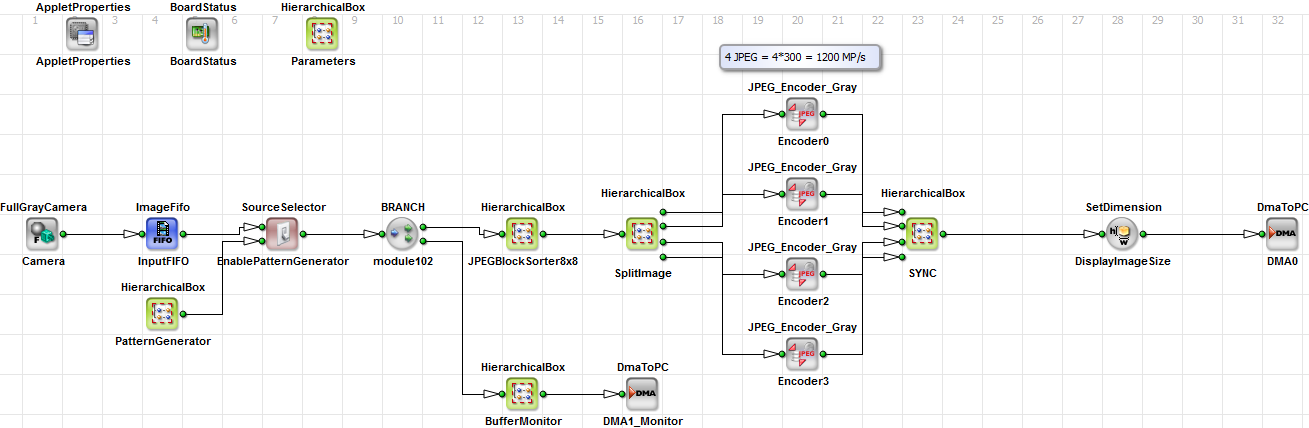
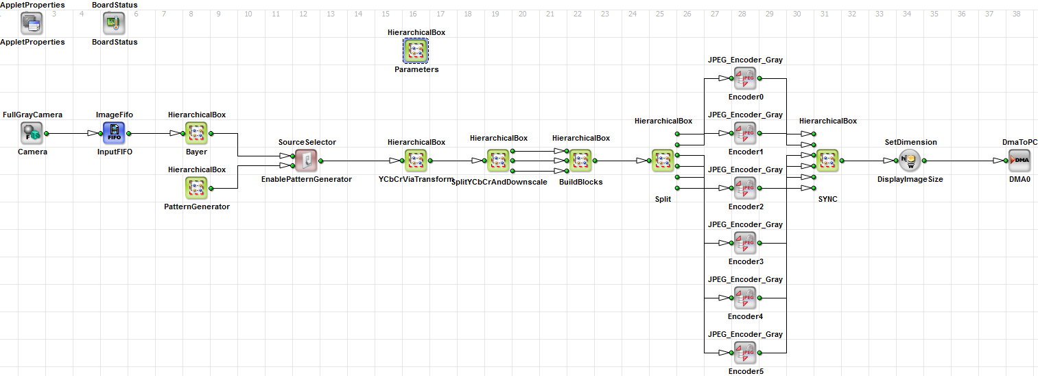
In Fig. 274 you can see the general applet. For the compression there are three interesting hierarchical boxes (JPEGBlockSorter8x8, SplitImage and SYNC).
In JPEGBlockSorter8x8(Fig. 275) the data of eight lines is rearanged to blocks of 8x8 pixel. These blocks are sent consecutively.
To keep the image handy the dimensions are kept the same.
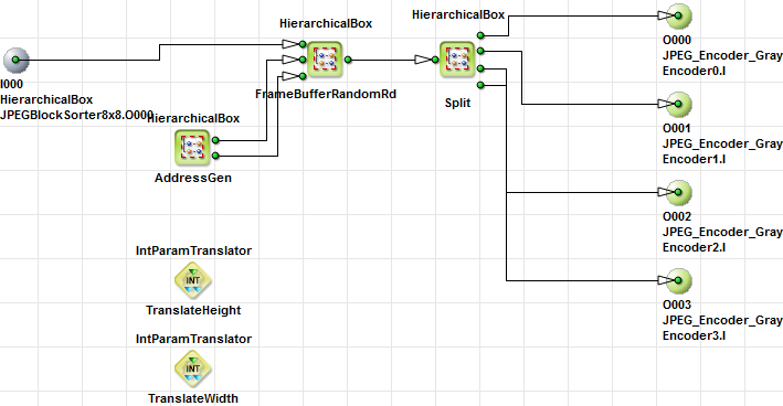
SplitImage(Fig. 277) saves the image to the DRAM and rearanges the lines in a way, that the four consecutive lines address four independend MCU-block-lines.
In this way for streams of MCU-block-lines can be split and send to 4 independend encoders.
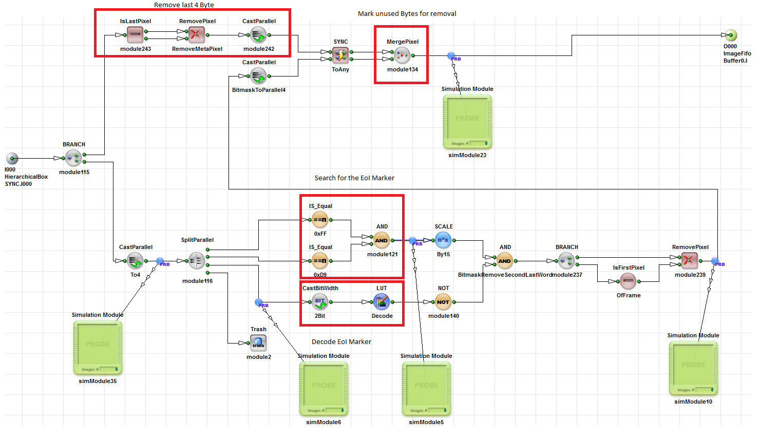
SYNC collects the encoded streams, replaces the information tag at the end by a restart marker and appends all lines to an image.
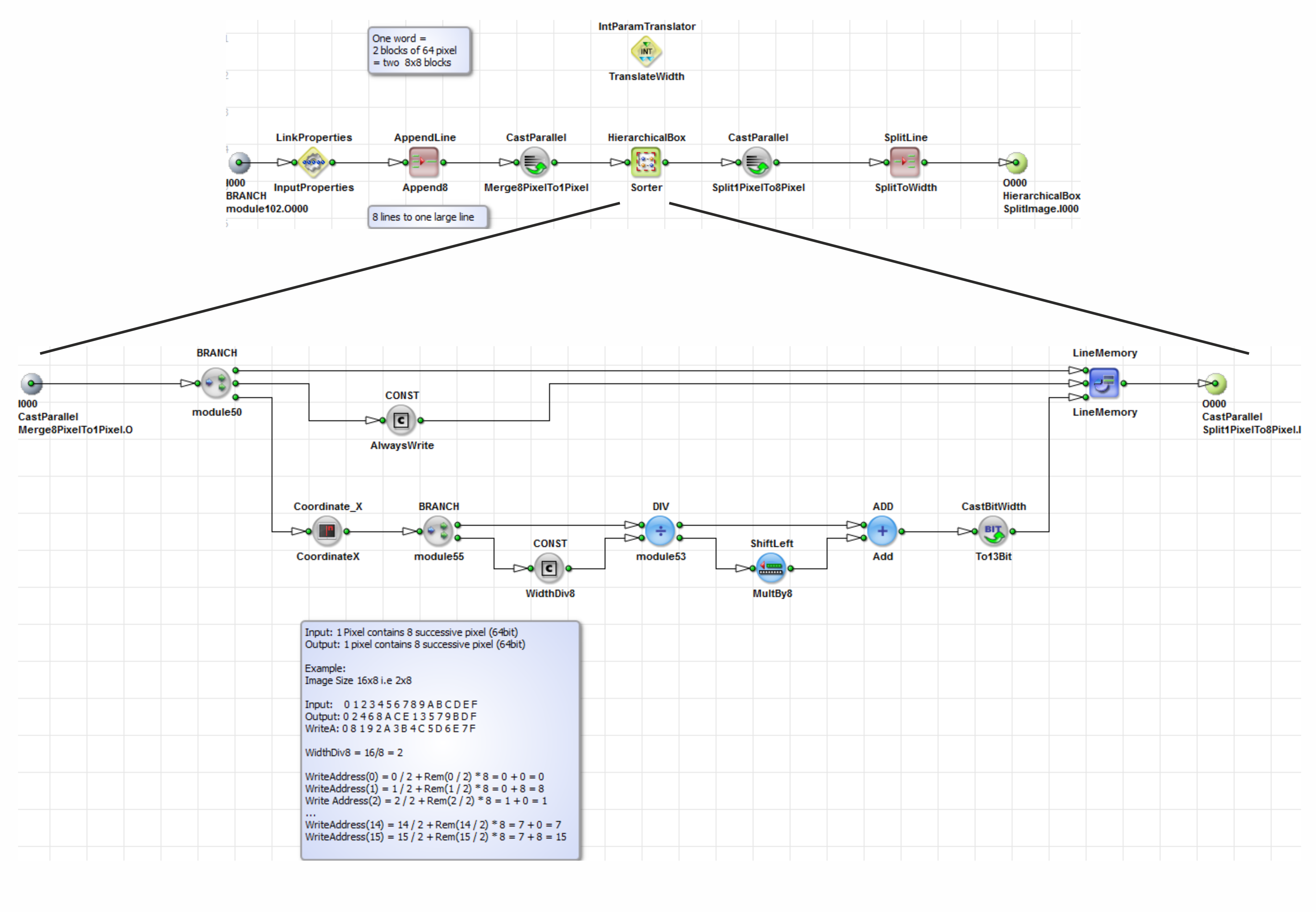
First eight pixel are appended to one "block-pixel". In the Sort Box these "block-pixel" are arranged in a way that the block pixel of each line follow after another as shown in Fig. 276
The SplitImage(Fig. 277) box rearanges the lines from the JPEGBlockSorter8x8(Fig. 275) into a scheme,
where always four blocks are separatly transmitted. Each block consists of eight lines. This procedure is repeated till
all lines are transmitted.
In the Split box the image is split into four images. This is done by removing all lines from each link that doesn't belong to the image.
These sub images are split
to images of the height eight, so that the applet can insert restart intervals at the end of eight lines.
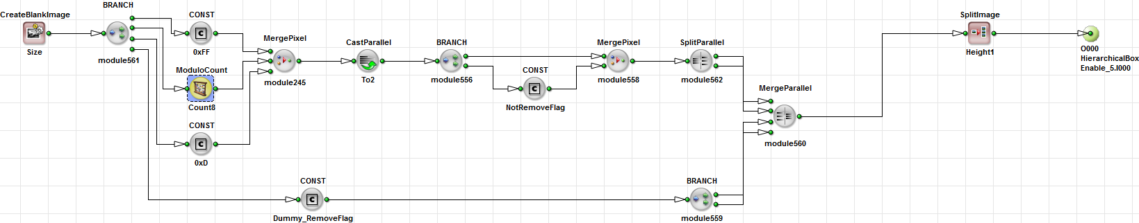
The SYNC box combines the streams of each JPEG_Converter into one image. This is done in three steps. First the final bytes (0xFFD9 - End of Image Marker + Informations from the operator) are marked for removal. This is done in the Box RemoveFillByte(Fig. 278). Second restart markers are added in between the blocks. Restart markers in a JPEG stream are in a structure: "0xFFDx", where x is a value from 0 to 7 counting round and robbin. This is done in the Box RestartMarker(Fig. 275). Third unused Bytes are removed.
For the image data you get out of this applet you need to add restart information to the header. This is done by adding the DRI Marker (0xFF DD) to the header.
This example is basically the same as the gray example. The differences are:
1. RGB data from a Bayer conversion is converted to the YCrCb colorspace.
2. Cr and Cb components are subsampled.
3. The separated images are buffered in a separate buffer. In order to sort the lines to six converters without inserting
dummy lines an independend sorting buffer is needed.
4. Sync needs to be split into three different images of different height.
In order to use restart intervals in a subsampled image the sampling factor needs to be adjusted to the minimum number of MCUs in a channel. We use a 4:2:0 subsampling. This means we have only half the line width in the Cr and Cb image. That's why lines need to be split in half in the Y image as well in order to get all restart markers in the same place.
